
 Back in the not-so-distant past, if you were patient and knowledgeable enough, you could reverse engineer the behavior of almost any electronic device simply by inspecting it carefully and understanding the circuitry. But those days are rapidly ending. Today, virtually every aspect of complex electronic hardware is controlled by microprocessors and software, and while that's generally good news for functionality, it's also bad news for security (and for having any chance of being sure what, exactly, your gadgets are doing, for that matter). For devices like smartphones, software runs almost every aspect of the user interface, including how and when it's powered on and off, and, for that matter, what being "off" actually means.
Complex software is, to put it mildly, hard to get right (for details, see almost any other posting on this or any other security blog). Especially for gadgets that are rich with microphones, cameras, location and environmental sensors, and communication links (such as, you know, smartphones), errors and security vulnerabilities in the software that controls them can have serious privacy implications.
The difficulty of reliably turning software-based devices completely off is no longer merely a hypothetical issue. Some vendors have even recognized it as a marketable feature. For example, certain Apple iPhones will continue to transmit "Find My Device" tracking beacons even after they've ostensibly been powered off. Misbehaving or malicious software could enable similar behavior even on devices that don't "officially" support it, creating the potential for malware that turns your phone into a permanently on surreptitious tracking device, no matter whether you think you've turned it off. Compounding these risks are the non-removable batteries used in many of the latest smartphones.
Sometimes, you might really want to make sure something is genuinely isolated from the world around it, even if the software running on it has other ideas. For the radios in phones (which can transmit and receive cellular, wifi, bluetooth, and near field communication signals and receive GPS location signals), we can accomplish this by encasing the device inside a small Faraday cage.
A Faraday cage severely attenuates radio signals going in or out of it. It can be used to assure that an untrustworthy device (like a cellphone) isn't transmitting or receiving signals when it shouldn't be. A Faraday cage is simple in principle: it's just a solid conductive container that completely encloses the signal source, such that the RF voltage differential between any two points on the cage is always zero. But actually constructing one that works well in practice can be challenging. Any opening can create a junction that acts as an RF feed and dramatically reduces the effective attenuation.
There are somewhat pricey (USD40-USD80) commercial Faraday pouches made specifically for cell phones, and there are a variety of improvised shielding methods that make the rounds as Internet folklore. The question is, then, how well do they actually work? It can be hard to reliably tell without access to a fairly specialized RF test lab. But fortunately, I sort of have one of those. While I can't compete with a full-scale commercial EMC test lab, my modest setup can make moderately accurate measurements of the signal attenuation provided by various commercial shielding pouches and home-brewed designs at most of the frequencies we care about.
I tested three commercial pouches as well as three commonly-recommended makeshift shielding methods. Read on for the results. (Note that I have no connection with any vendor mentioned here, and I do not endorse any of the products discussed for any particular purpose. Caveat emptor.)
Methodology and Setup
The purpose of a Faraday cage is to reduce the strength of (attenuate) radio signals traveling between the outside of the cage and the inside of the cage down to a level that makes them effectively undetectable, even to an adversary. An "ideal" Faraday cage would provide infinite attenuation, but, in the real physical world, nothing we can actually build will be perfect. So we must settle for a level of attenuation that's sufficient to reduce a practical signal to below the level at which it can be detected at a reasonable distance. Fortunately, the signals coming from cellphones start out relatively weak as these things go (less than one Watt of RF power), as are many of the signals they receive to geolocate themselves (such as those coming from GPS satellites). The signals sent from cellular base stations are a bit stronger, but still within the range that they can potentially be attenuated down to a level that makes them undetectable.
So how much attenuation do we need? RF engineers usually measure attenuation in decibels (dB), which is a logarithmic unit that expresses the ratio of the difference in magnitude of two signals. 20 dB represents a change of a factor of 10 in amplitude (volts), while 40 dB is a factor of 100, 60 dB a factor of 1000, and so on. (0 dB represents no change at all). So 20dB of attenuation converts a 1 volt signal into a 0.1 volt signal, while 80 dB attenuation converts 1 volt into just 0.0001 volts. (The ratios are different when measuring power levels (Watts), but the idea is the same.)
What does that mean for us? Conservatively, as a practical matter, 80 or 90 dB of attenuation is plenty, unless your phone is within a few feet of a cell tower antenna (which is an unsafe place for your body to be in any case). So we want our Faraday pouch to provide at least that much attenuation at the frequencies of concern.
Cell phones communicate over a wide range of frequencies, most of which range from just below 1 GHz to about 6 GHz. The latest 5G networks can also use "millimeter wave" frequencies above that, but they aren't currently widely deployed (and require very specialized and expensive gear to make accurate measurements.) So we'll be focusing here on frequencies from 1 to 6 GHz.
How do we measure attenuation? We need to compare the strength of a signal at a given frequency passing through the wall of the pouch with the strength of the same signal at the same distance with no pouch. The difference (in dB) is the attenuation provided by the pouch at that frequency. So we need to set up a controlled experiment with a signal source and an RF field strength meter that lets us measure signal levels with and without the pouch under test present.
There are two ways to do this. One is to put the signal source outside the pouch and the meter inside the pouch, and the other is to put the meter outside the pouch and the signal source inside the pouch. The two ways are equivalent; Faraday cages are, for our purposes, effectively non-directional. My signal generator is much smaller than my measurement receiver, so I opted to go with the first setup.
Our test setup, then, needs to place our signal generator (with an antenna) a fixed distance away from our measurement receiver (also with an antenna), in an RF environment free enough from outside interference that we can take accurate signal strength measurements of both the original signal (with no pouch) and the (hopefully much weaker) signals measured through the various pouches.
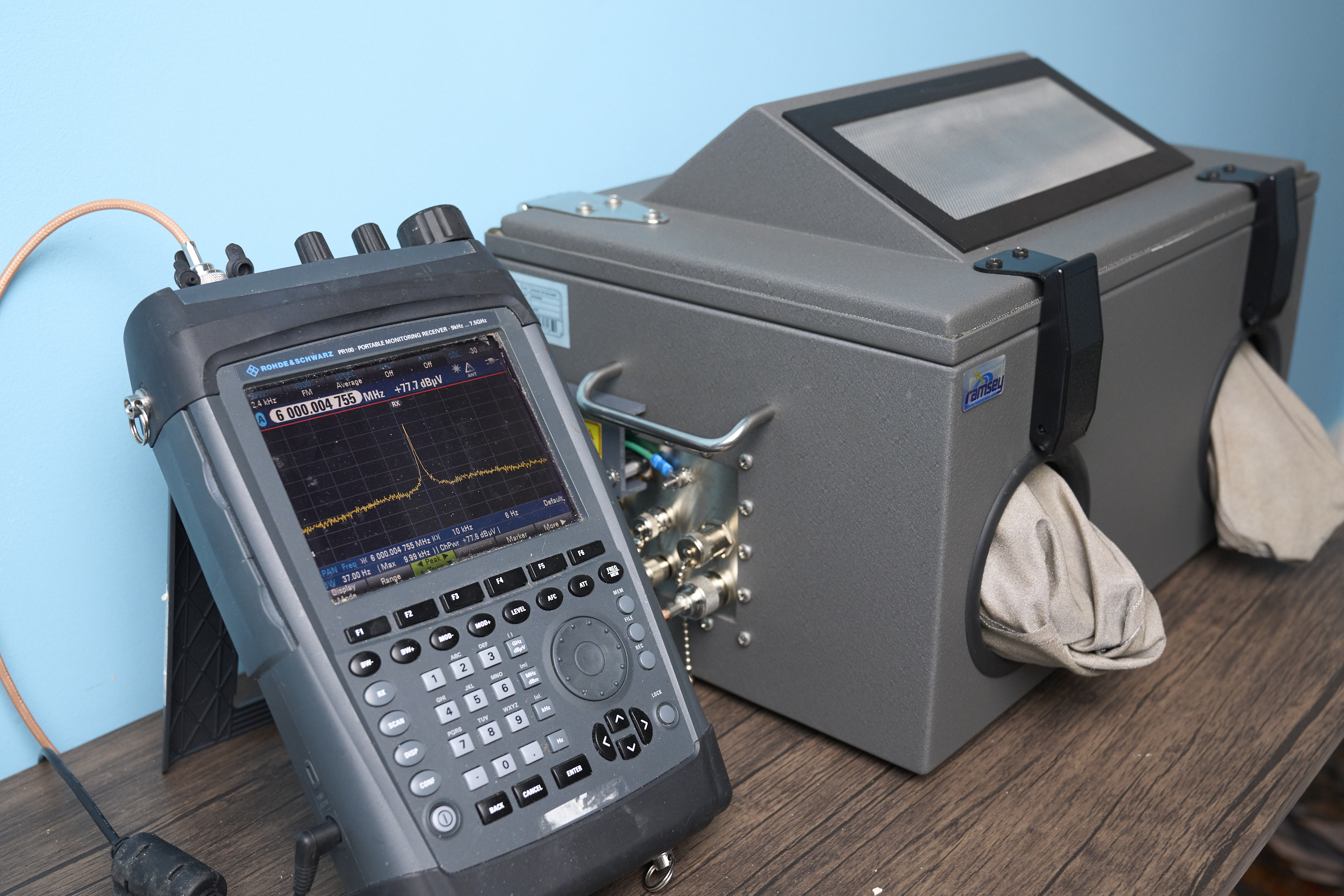
The instrument we used for our signal strength measurements was a Rhode and Schwarz model PR100 measurement receiver. This radio is designed for detecting weak signals and making accurate field strength measurements up to 7.5 GHz. Usefully, it can measure signal strength directly in dBµV (dB relative to a 1 microvolt strength). This is very convenient for our purposes, since we can calculate attenuation in dB simply by subtracting one dBµV measurement from the other.
Our signal source was an ERASynth Micro signal generator, which I got from Crowd Supply for about $300 a while back. It (plus a small antenna and USB battery) can fit (snugly) inside commercial cellphone-size Faraday pouches. It puts out a clean signal at any frequency up to 6GHz at over 10dBm (10 mW) which makes it ideal for experiments like this.
The antennas on both the receiver and the signal generator were cheap SMA antennas intended for Bluetooth that I had lying around in my junk box. While not resonant over the entire frequency range (1-6 GHz) we were measuring, they were still sufficiently efficient to be usable. (Since we're only concerned with relative measurements, we don't care about the exact radiation efficiency of the antennas, as long as we use the same ones in the same orientation throughout all the tests.) They're 40mm long, which made them small enough to fit in tight spaces. (The antenna size will also be important for calculating the minimum far field distance at which we can take reliable measurements.)
Note that making signal strength measurements involves sending (low power) radio signals through the air between the signal generator and the receiver. That makes the measurements potentially vulnerable to interference from other signal and RF noise sources in the local area. To reduce the effects of noise, we make all our measurements inside a another, larger, Faraday cage, a special "RF test chamber" designed to provide an isolated RF environment for these sorts of experiments.
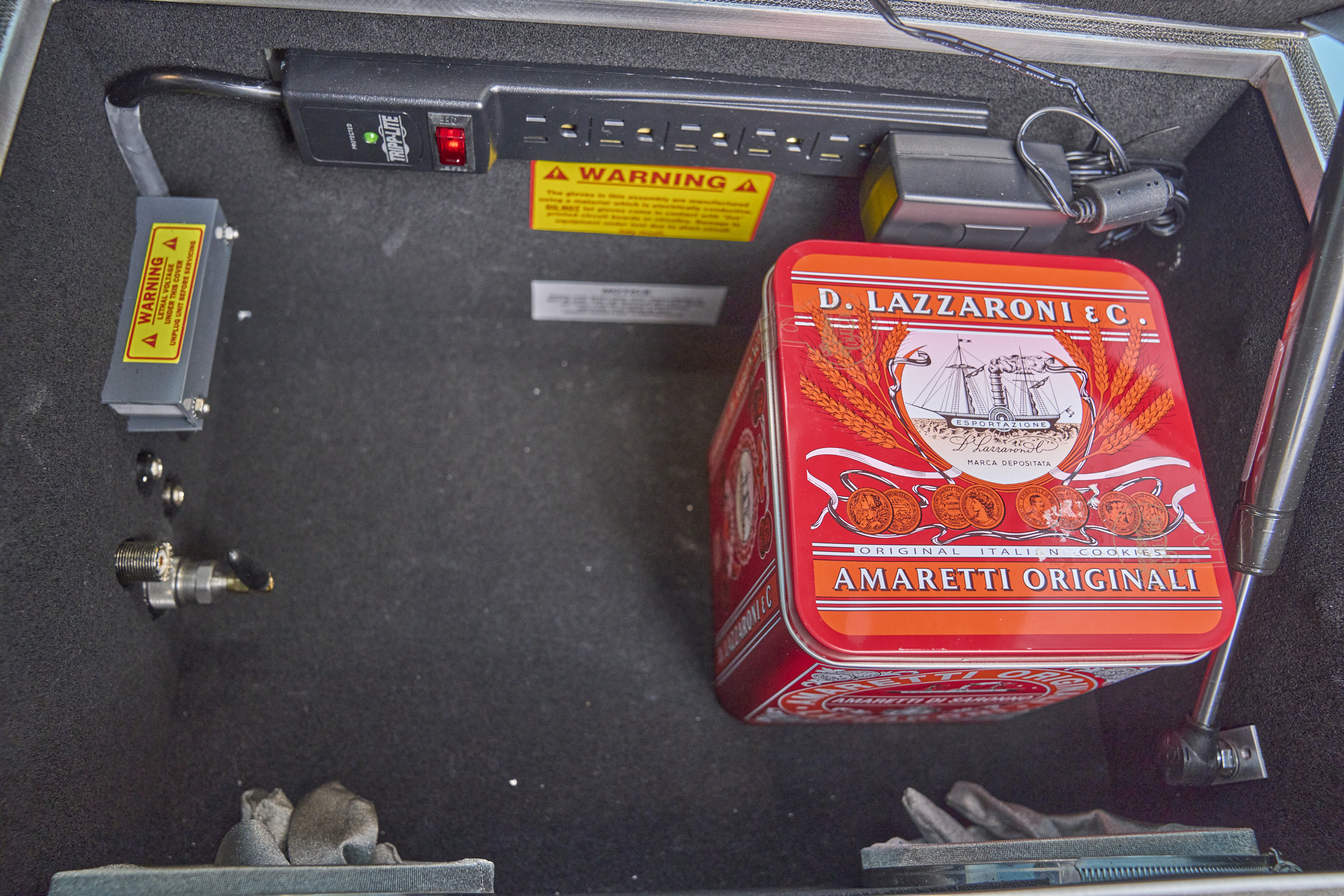
Our RF test chamber was a Ramsey Electronics model STE3000B. This is basically a carefully constructed breadbox-sized Faraday cage equipped with RF connectors that allow connecting external instruments (such as our receiver) to components isolated inside the box (where we want the receiver's antenna and the signal generator and pouches we were testing). This particular model also provides filtered AC power and a conductive "glove box" that allows you to manipulate objects and controls located inside the box while it's closed, but we didn't use those features for these experiments. It's lined with RF-absorbent foam, though that's not quite sufficient to make it a true anechoic chamber (which would be preferable for experiments like this).
RF signals naturally attenuate with distance, and so we need to make sure to maintain a constant measurement distance when calculating the attenuation of our pouches under test. We positioned the signal generator antenna 300mm from the receiver antenna inside the chamber, and we took care to keep the placement the same during all our subsequent measurements with the generator inside the various pouches.
A note about this distance: RF signals behave differently when measured very close to the signal source, called the "near field region". We want to keep our signal source and receiver sufficiently separated that they're well outside the near field, so that our measurements would be in the "far field". (The far field is also where we'd expect an adversary's receivers to be located in practice.) The size of the near field depends on the size of the antenna and the frequency. Fortunately, at the frequencies involved and with the 40mm antennas we used, the near field region is pretty small, extending at most only 64mm. Our 300mm of separation therefore conservatively ensured we were measuring only in the far field at every frequency.
Disclaimer: While this is about as careful a setup as I can create with the equipment I have available, it's not at all perfect. A commercial EMC testing lab could surely do better. The generator and receiver aren't perfectly stable over time. The distances at which the measurements were taken likely varied by perhaps 10 or 15 mm across tests. The RF chamber, while somewhat anechoic, still permits some internal signal reflections that could affect measurements. And there was a degree of subjective human interpretation required as measurements fluctuated and settled. So these measurements should be regarded as approximations, with the true attenuation values being only within about 10 dB of those I calculated. RF is hard.
Baseline Measurements
Our first step was to take baseline measurements of signal levels with the generator outside any Faraday pouch at each of the various frequencies of interest.
The signal strengths we measure here will be the values from which we'll subtract the measurements we later make with the generator inside the pouches under test to calculate their attenuation. We'll also measure the noise floor level (with no generated signal present) at each frequency. The difference between the noise floor measurement and the signal measurement (the "dynamic range") will tell us the maximum attenuation we're able to measure with this setup.
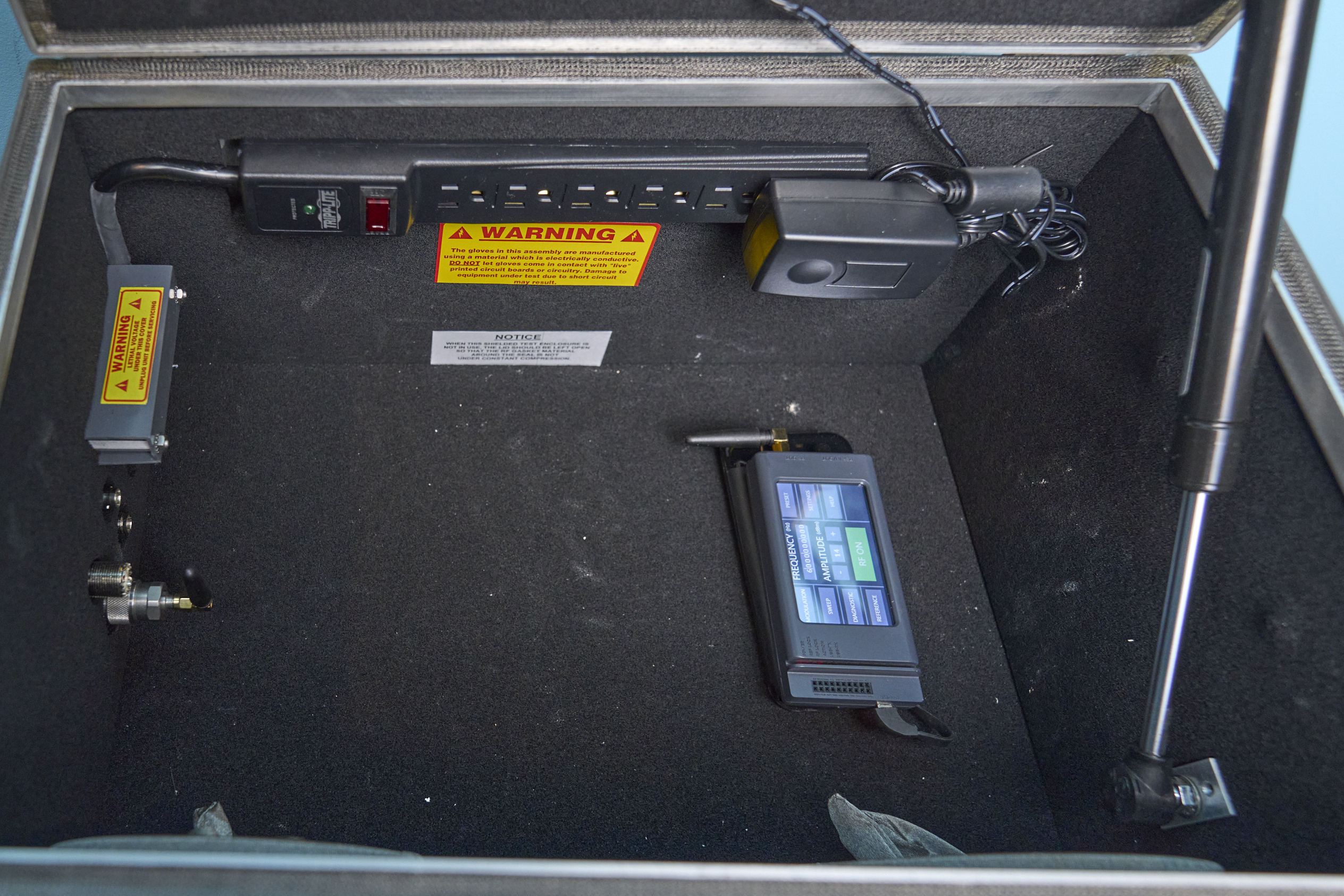
Measurements were made at 1, 2, 3. 4, 5, and 6 GHz, with the generator emitting 10 dBm power, except at 1 GHz and 6 GHz, where we used 14 and 15 dBm power, respectively, to partly compensate for reduced antenna efficiency at the edges of the range. Our measurements were as follows:
| Frequency | Noise Floor (N) | Signal strength (S) | Dynamic range (S-N) |
|---|---|---|---|
| (GHz) | (dBµV) | (dBµV) | (dB) |
| 1.0 | -26.3 | 79.2 | 105.5 |
| 2.0 | -28.1 | 85.6 | 113.7 |
| 3.0 | -25.8 | 88.3 | 114.1 |
| 4.0 | -20.8 | 81.8 | 102.6 |
| 5.0 | -21.2 | 79.4 | 100.6 |
| 6.0 | -20.6 | 77.9 | 98.5 |
Commercial Pouch 1: EDEC Window Pouch
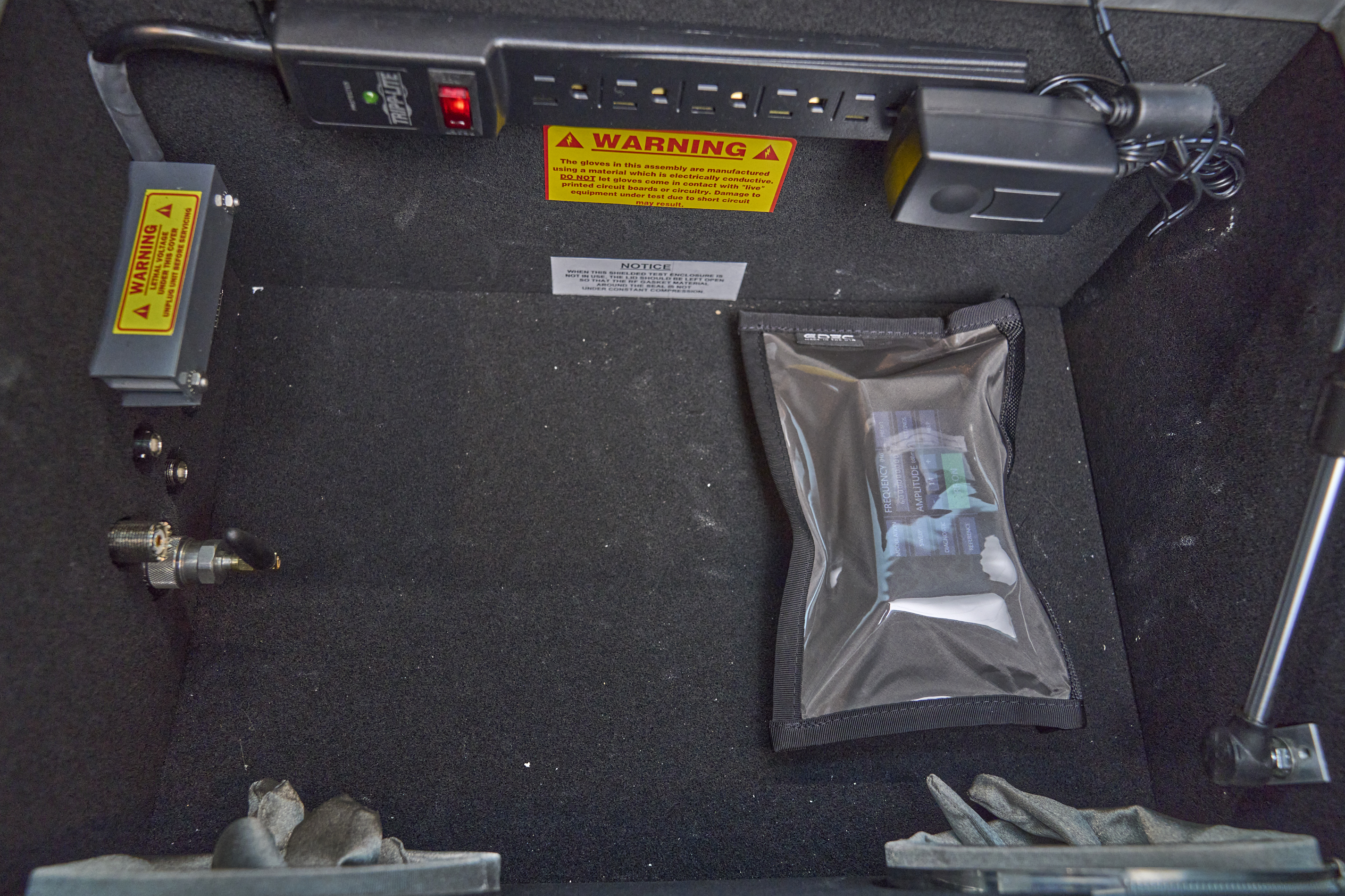 The first pouch we tested was a commercial product, the EDEC cellphone "window" pouch. This pouch has exposes a visible window (through a dense conductive fabric) to allow you to see a phone display inside a pouch. EDEC sells a variety of pouches on their web site. as well as RF shielding fabric, tape, and related products.
The table below (and subsequent tables below) gives, for each frequency tested, the baseline measurement (taken from the table above), the measured signal strength with the generator in the pouch, and the calculated pouch attenuation in dB.
| Frequency | Baseline (B) | Signal strength (S) | Attenuation (B-S) |
|---|---|---|---|
| (GHz) | (dBµV) | (dBµV) | (dB) |
| 1.0 | 79.2 | -22.2 | 101.4 |
| 2.0 | 85.6 | -19.5 | 105.1 |
| 3.0 | 88.3 | -15.4 | 103.7 |
| 4.0 | 81.8 | 2.4 | 79.4 |
| 5.0 | 79.4 | 10.1 | 69.3 |
| 6.0 | 77.9 | 11.0 | 66.9 |
This pouch performed quite well (over 100 dB attenuation) through 3 GHz, but performance dropped off sharply at 4 GHz and higher. Fearing I had a defective or damaged pouch, I tried a second sample but got almost identical results. This pouch is certainly more than adequate to attenuate Bluetooth, 2.4 GHz wifi, GPS, and most cellular signals below 3GHz, but may be inadequate for protecting against surreptitious exfiltration of signals at higher frequencies. (I suspect the performance at higher frequencies may be have been degraded by small gaps left by this pouch's Velcro closure mechanism).
Commercial Pouch 2: EDEC OffGrid Pouch
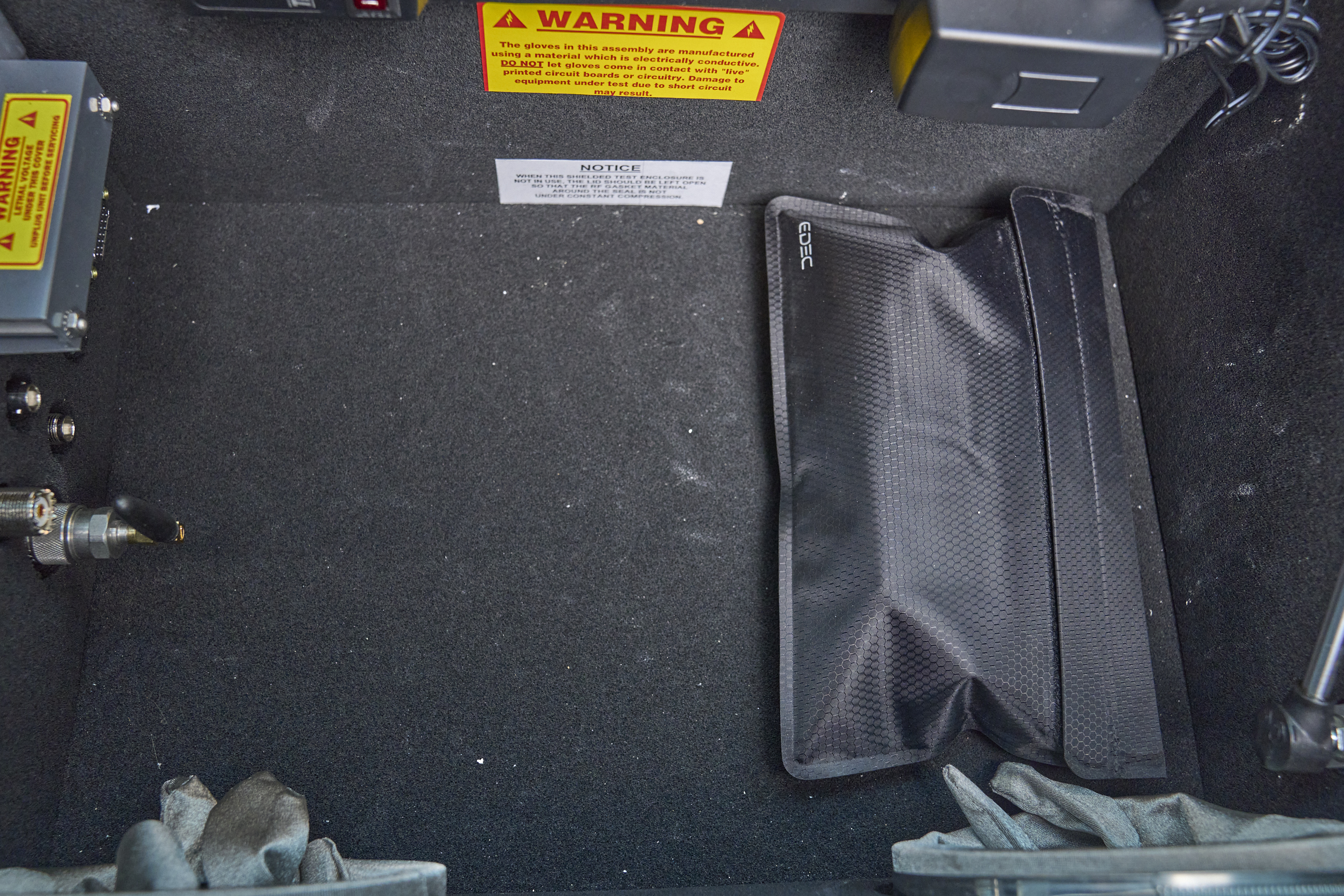 Our next pouch came from the same vendor and is, I believe, a more recent model. It's of lighter construction, and employs a different closure mechanism with both Velcro and a magnet. There's no viewing window.
| Frequency | Baseline (B) | Signal strength (S) | Attenuation (B-S) |
|---|---|---|---|
| (GHz) | (dBµV) | (dBµV) | (dB) |
| 1.0 | 79.2 | -22.6 | 101.8 |
| 2.0 | 85.6 | -25.2 | 110.8 |
| 3.0 | 88.3 | -17.7 | 106.0 |
| 4.0 | 81.8 | -18.7 | 100.5 |
| 5.0 | 79.4 | -18.5 | 97.9 |
| 6.0 | 77.9 | -11.5 | 89.4 |
This pouch performed extremely well across the entire range, despite the lighter-weight construction compared with the "window" model of the same brand tested above. The attenuation at these frequencies is likely more than sufficient to prevent signal exfiltration in practice.
Commercial Pouch 3: Mission Darkness Window Pouch
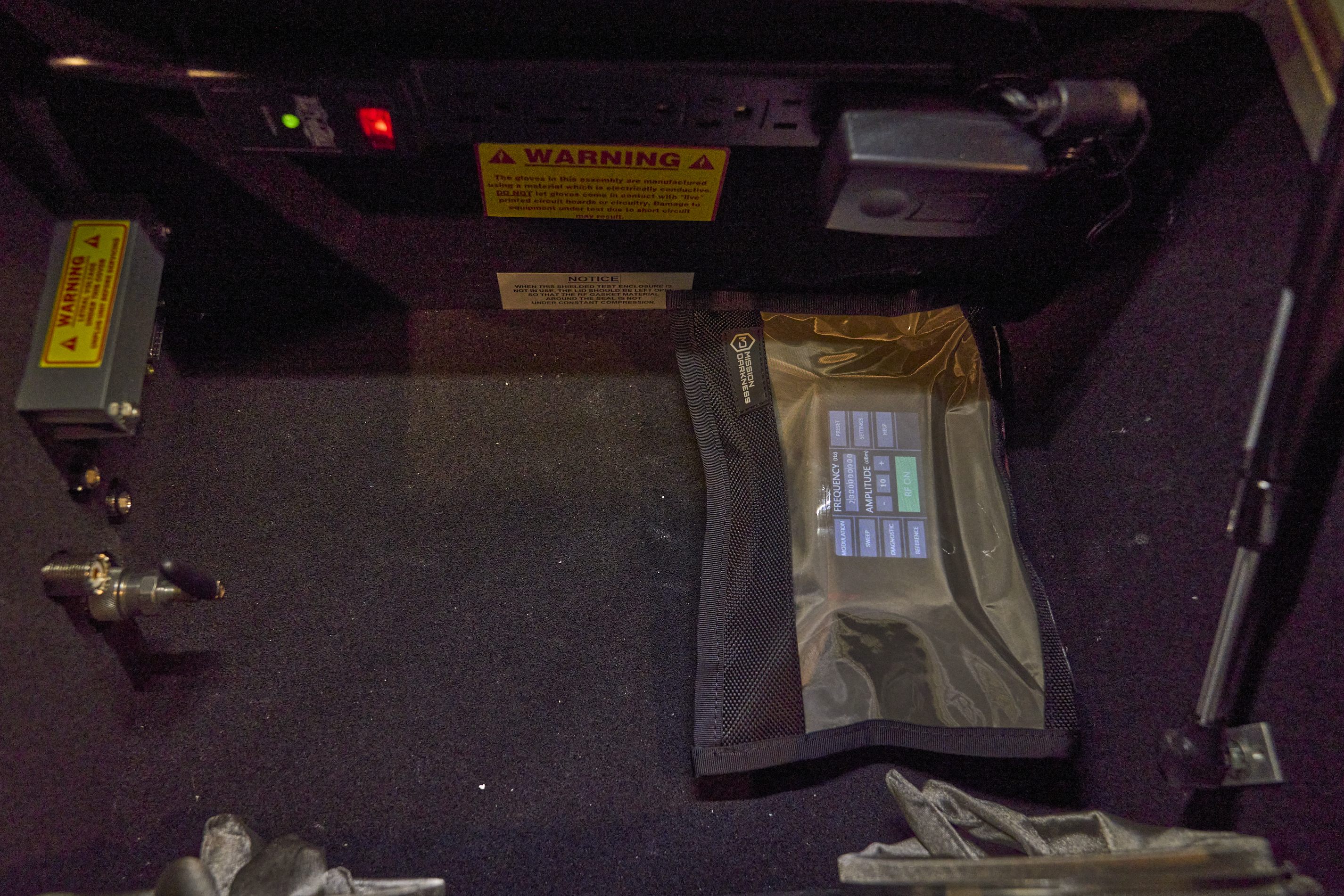 "Mission Darkness" is another vendor of Faraday pouches. They're sold on Amazon as well as on the company's web site. The Mission Darkness "window" pouch is similar in appearance to the EDEC window pouch, and employs a similar double-folded Velcro closure. However, as we will see, it performed quite differently.
| Frequency | Baseline (B) | Signal strength (S) | Attenuation (B-S) |
|---|---|---|---|
| (GHz) | (dBµV) | (dBµV) | (dB) |
| 1.0 | 79.2 | -25.7 | 104.9 |
| 2.0 | 85.6 | -24.6 | 110.2 |
| 3.0 | 88.3 | -20.8 | 109.1 |
| 4.0 | 81.8 | -18.8 | 100.6 |
| 5.0 | 79.4 | -17.7 | 97.1 |
| 6.0 | 77.9 | -18.7 | 96.6 |
Makeshift Pouch 1: Electrostatic and Mylar Bags
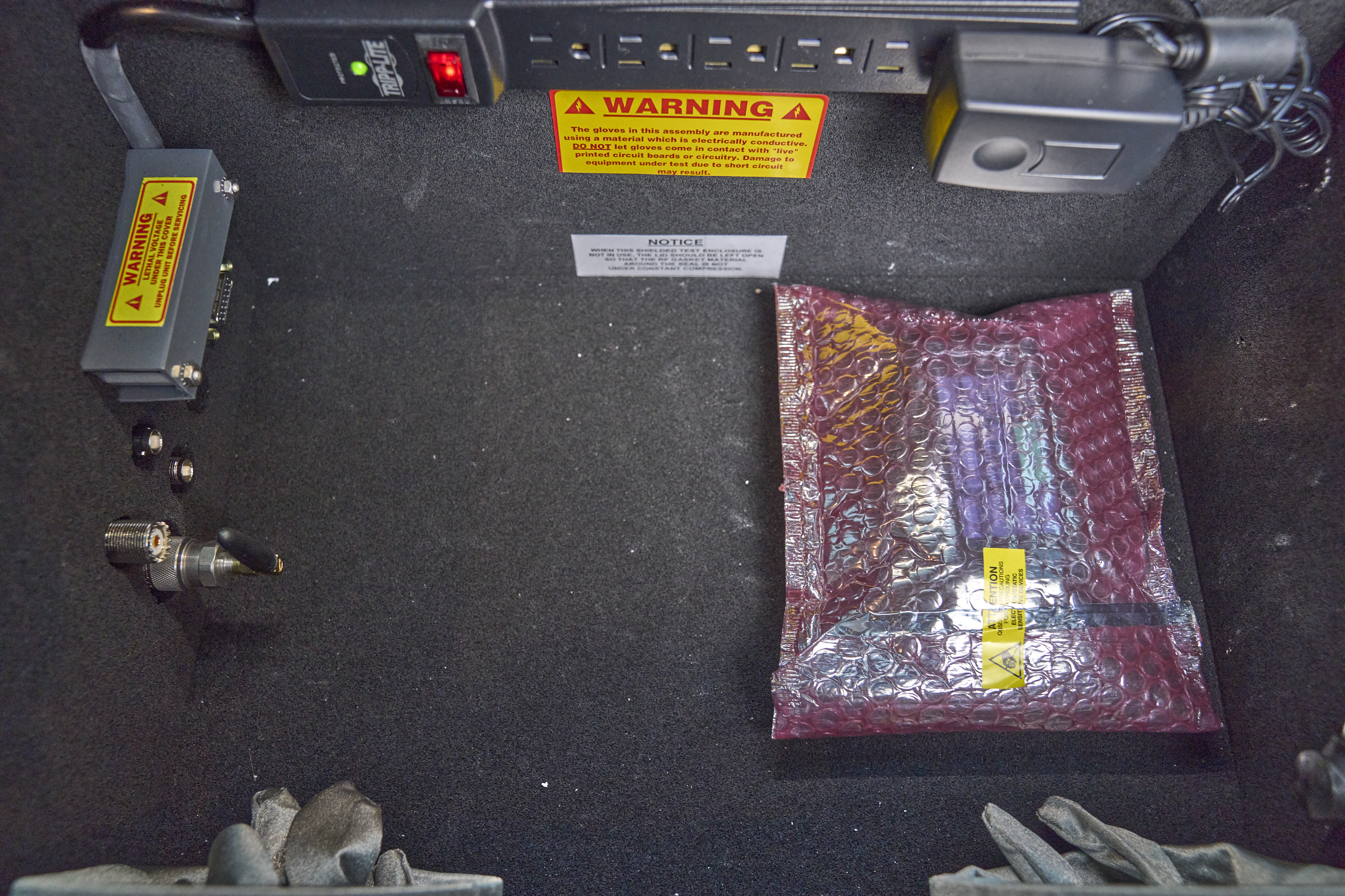 Conductive mylar bags are often used to protect sensitive electronics from static discharges. But do they work as Faraday cages? If you work with electronic components, you likely have a drawer full of them already, making them effectively free. I measured several; shown here are the results with a nice padded ESD bag (which was similar in performance to the unpadded mylar bags but nicer looking).
| Frequency | Baseline (B) | Signal strength (S) | Attenuation (B-S) |
|---|---|---|---|
| (GHz) | (dBµV) | (dBµV) | (dB) |
| 1.0 | 79.2 | 72.2 | 7.0 |
| 2.0 | 85.6 | 79.7 | 6.9 |
| 3.0 | 88.3 | 80.7 | 7.6 |
| 4.0 | 81.8 | 74.1 | 7.7 |
| 5.0 | 79.4 | 72.6 | 6.8 |
| 6.0 | 77.9 | 69.1 | 8.8 |
In no instance did any of my mylar/ESD bags provide more than about 9 dB of attenuation. If your mylar bags are free, expect to get what you pay for. Not recommended.
Makeshift Pouch 2: Metal Cookie Tin
 Metal cookie tins seem promising as Faraday cages. They're made of metal that completely encloses the contents, and are produced by a reasonably consistent commercial process. I tested a medium-size tin that fit the signal generator and that also fit inside the RF test enclosure. Note that the position of the tin was extremely critical; only a few mm of movement produced several dB different measurements. This likely had to do with the introduction of the relatively large RF reflective surface of the tin within the test rig.
| Frequency | Baseline (B) | Signal strength (S) | Attenuation (B-S) |
|---|---|---|---|
| (GHz) | (dBµV) | (dBµV) | (dB) |
| 1.0 | 79.2 | 40.4 | 38.8 |
| 2.0 | 85.6 | 42.1 | 43.5 |
| 3.0 | 88.3 | 49.4 | 38.9 |
| 4.0 | 81.8 | 48.6 | 33.2 |
| 5.0 | 79.4 | 49.3 | 30.1 |
| 6.0 | 77.9 | 49.1 | 28.8 |
While the cookie tin performed much better than the mylar bags, and could provide a modicum of useful attenuation under some circumstances, it was not sufficient to provide meaningful assurance of signal isolation at any frequency. However, it was unique among the containers tested in providing tasty snacks during measurements.
Makeshift Pouch 3: Heavy Duty Aluminum Foil
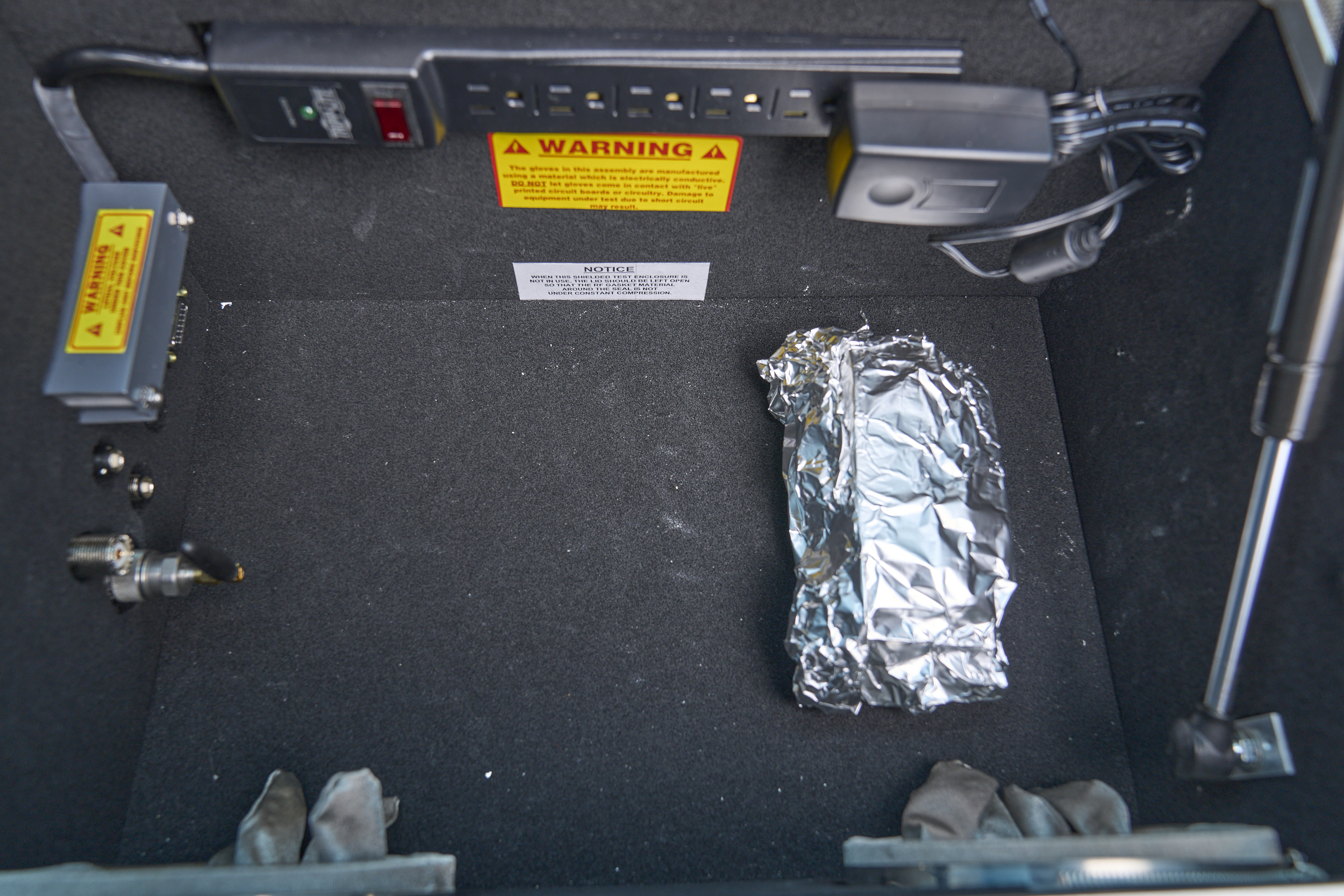 "Wrap it in tin foil" is perhaps the most common advice found on the Internet for making a makeshift Faraday cage. In my experiments, I found I could sometimes achieve approximately 90 dB attenuation by carefully wrapping the generator in foil and double folding the seams on all sides, which is quite good (comparable to commercial pouches). Unfortunately the results were extremely inconsistent and difficult to replicate. The same technique that produced 90 dB attenuation in one test would produce only 50 dB the next time, with no visually obvious differences. It is extremely difficult to reliably obtain a good RF seam, at least with the kitchen-grade foil I used.
Compounding the problem is that there's no practical way to field test an improvised foil enclosure. Because it's essentially single-use, you would have no way to tell whether you've managed to fold and seal it adequately well. (And even if you could, you'd destroy your work as soon as you open the pouch.) So despite excellent best case results, aluminum foil appears to be impractical for real-world use. (There's no point in providing a table of measurements here; it would be meaningless).
Conclusions
If it wasn't already clear, making accurate measurements of the attenuation provided by a Faraday bag involves expensive gear and fussy technique. But you probably don't need accurate measurements for most purposes.
A quick and likely reliable "go/no go test" can be done with an Apple AirTag and an iPhone: drop the AirTag in the bag under test, and see if the phone can locate it and activate its alarm (beware of caching in the FindMy app when doing this). This test won't tell you the exact attenuation level, of course, but it will tell you if the attenuation is sufficient for most practical purposes. It can also detect whether an otherwise good bag has been damaged and compromised.
A less useful test is to simply put a phone in a container and see if it rings when called. But this has a serious limitation: you likely don't know how far away the cell tower is, what frequency it's using, or its signal strength. So even if a container passes this test in one location, there's no guarantee the shielding will prove adequate somewhere else.
At least in the frequency ranges I tested, two commercial Faraday pouches (the EDEC OffGrid and Mission Darkness Window pouches) yielded excellent performance sufficient to provide assurance of signal isolation under most real-world circumstances. None of the makeshift solutions consistently did nearly as well, although aluminum foil can, under ideal circumstances (that are difficult to replicate) sometimes provide comparable levels of attenuation.
5G cellular services add a new wrinkle in their use of millimeter-wave bands (over 20 GHz) that fall outside the range of my measurement setup. These frequencies have different propagation and absorption characteristics from the lower GHz bands we tested here. It is possible that the containers tested here perform similarly at those frequences, but it's also possible that they would do much worse. Fortunately, the mm wave 5G bands are not yet widely used in the cellular infrastructure in the US, but that could change rapidly. More testing will be required once that happens.
It's important to recognize that a Faraday pouch, no matter how effective, only prevents radio communication. A malicious phone might do harmful things that don't involve the use of radio. For example, it could still record audio, and wait for the phone to come out of the pouch to exfiltrate it. So for the truly paranoid, even the best possible Faraday cage might not provide sufficient protection.
The use case for Faraday pouches is narrow, and you have to understand the threat against which you're protecting for them to provide any benefit. For example, if you're concerned about being tracked to some sensitive meeting, you need to isolate the phone before traveling there, not merely once you've arrived.
Most of us almost certainly don't need a Faraday pouch. But for some people under some circumstances (from abused partners to intelligence operators), threats like location tracking can be serious and can expose them to real danger. They deserve effective, measureable protection.